Thursday 5 July 2018

DESIGN METHODS FOR BEAMS AND COLUMNS


DESIGN METHODS FOR BEAMS AND COLUMNS


A number of different design methods have been used for reinforced concrete construction. The three most common are working-stress design, ultimate-strength

design, and strength design method. Each method has its backers and supporters.


For actual designs the latest edition of the ACI Code should be consulted.

Beams

Concrete beams may be considered to be of three principal types: (1) rectangular beams with tensile reinforcing only, (2) T-beams with tensile reinforcing

only, and (3) beams with tensile and compressive reinforcing.

Rectangular Beams with Tensile Reinforcing Only This type of beam includes

slabs, for which the beam width equals 12 in (305 mm) when the moment and

shear are expressed per foot (m) of width. The stresses in the concrete and steel

are, using working-stress design formulas,


CONCRETE FORMULAS
Cross section of beam Stress diagram
 
FIGURE 5.1 Rectangular concrete beam with tensile reinforcing only

ABLE 5.1Guides to Depth of Reinforced
Concrete Beam*
Member
d
Roof and floor slabsl/25
Light beamsl/15
Heavy beams and girdersl/12–l/10
*is the span of the beam or slab in inches (millimeters

The width of a beam should be at least l/32.

TABLE 5.2 Coefficients Kkj, and for Rectangular Sections*

Values of Kkj, and for commonly used stresses are given in Table 5.2.

T-Beams with Tensile Reinforcing Only When a concrete slab is constructed

monolithically with the supporting concrete beams, a portion of the slab acts as the

upper flange of the beam. The effective flange width should not exceed (1) onefourth the span of the beam, (2) the width of the web portion of the beam plus 16

times the thickness of the slab, or (3) the center-to-center distance between beams.

T-beams where the upper flange is not a portion of a slab should have a flange

thickness not less than one-half the width of the web and a flange width not more
than four times the width of the web. For preliminary designs, the preceding
formulas given for rectangular beams with tensile reinforcing only can be used,
because the neutral axis is usually in, or near, the flange. The area of tensile
reinforcing is usually critical.
Beams with Tensile and Compressive Reinforcing Beams with compressive
reinforcing are generally used when the size of the beam is limited. The
allowable beam dimensions are used in the formulas given earlier to determine
the moment that could be carried by a beam without compressive reinforcement.
The reinforcing requirements may then be approximately determined from

Checking Stresses in Beams Beams designed using the preceding approximate

formulas should be checked to ensure that the actual stresses do not exceed the

allowable, and that the reinforcing is not excessive. This can be accomplished by

determining the moment of inertia of the beam. In this determination, the

concrete below the neutral axis should not be considered as stressed, whereas the

reinforcing steel should be transformed into an equivalent concrete section. For

tensile reinforcing, this transformation is made by multiplying the area Aby n,
the ratio of the modulus of elasticity of steel to that of concrete. For compressive
reinforcing, the area Asc is multiplied by 2(– 1). This factor includes allowances
for the concrete in compression replaced by the compressive reinforcing and for
the plastic flow of concrete. The neutral axis is then located by solving

FIGURE 5.2 Transformed section of concrete beam

  1. Columns
The principal columns in a structure should have a minimum diameter of 10 in
(255 mm) or, for rectangular columns, a minimum thickness of 8 in(203 mm) and
a minimum gross cross-sectional area of 96 in(61,935 mm2).
Short columns with closely spaced spiral reinforcing enclosing a circular
concrete core reinforced with vertical bars have a maximum allowable load of


Short Columns with Ties The maximum allowable load on short columns
reinforced with longitudinal bars and separate lateral ties is 85 percent of that given

Thursday 14 December 2017

Earthquake resistant building

An earthquake is the vibration, sometimes violent to the earth’s surface that follows a release of energy in the earth’s crust. This energy can be generated by a sudden dislocation of segments of the crust, by a volcanic eruption or even by a man made explosion. The dislocation of the crust causes most destructive earthquakes. The crust may first bend and then the stresses exceed the strength of rocks, they break. In the process of breaking, vibrations called seismic waves are generated. These waves travel outward from the source of the earthquake along the surface and through the earth at varying speeds depending on the material through which they move. These waves can cause disasters on the earth’s surface.
No structure on the planet can be constructed 100% earthquake proof; only its resistance to earthquake can be increased. Treatment is required to be given depending on the zone in which the particular site is located. Earthquake occurred in the recent past have raised various issues and have forced us to think about the disaster management. It has become essential to think right from planning stage to completion stage of a structure to avoid failure or to minimize the loss of property. Not only this, once the earthquake has occurred and disaster has taken place; how to use the debris to construct economical houses using this waste material without affecting their structural stability.
HOW EARTHQUAKE RESISTANT CONSTRUCTION IS DIFFERENT?
Since the magnitude of a future earthquake and shaking intensity expected at a particular site cannot be estimated with a reasonable accuracy, the seismic forces are difficult to quantify for the purposes of design. Further, the actual forces that can be generated in the structure during an earthquake are very large and designing the structure to respond elastically against these forces make it too expensive.
Therefore, in the earthquake resistant design post yield inelastic behavior is usually relied upon to dissipate the input seismic energy. Thus the design forces of earthquakes may be only a fraction of maximum (probable) forces generated if the structure is to remain elastic during the earthquake. For instance, the design seismic for buildings may at times be as low as one tenths of the maximum elastic seismic force. Thus, the earthquake resistant construction and design does not aim to achieve a structure that will not get damaged in a strong earthquake having low probability of occurrence; it aims to have a structure that will perform appropriately and without collapse in the event of such a shaking.
Ductility is the capacity of the structure to undergo deformation beyond yield without loosing much of its load carrying capacity. Higher is the ductility of the structure; more
is the reduction possible in its design seismic force over what one gets for linear elastic response. Ensuring ductility in a structure is a major concern in a seismic construction. 
Earthquake resistant building:
The engineers do not attempt to make earthquake proof buildings that will not get damaged even during the rare but strong earthquake; such buildings will be too robust and also too expensive. Instead, engineering intention is to make buildings earthquake resistant, such building resists the effects of ground shaking, although they may get damaged severely but would not collapse during the strong earthquake. Thus, safety of peoples and contents is assured in earthquake resistant buildings and thereby, a disaster is avoided. This is a major objective of seismic design codes through the world. 
Earthquake design philosophy:
The earthquake design philosophy may be summarized as follows:
 Under minor, but frequent shaking, the main members of the building that carry vertical and horizontal forces should not be damaged; however the building parts that do not carry load may sustain repairable damage.
 Under moderate but occasional shaking, the main member may sustain repairable damage, but the other parts of the building may be damaged such that they may even have to be replaced after the earthquake.

Friday 20 October 2017

Types of Brick Bonds


Types of Brick Bonds

Some of the different types of brick bonds are,
1. English bond,

2. Flemish bond,
3. Stretching bond,
4. Heading bond,
5. Garden wall bond,
6. Facing bond,
7. Raking bond,
8. Dutch bond,
9. English cross-bond,
10. Zig-Zag bond,
11. Silverlock’s bond.
1. English bond:

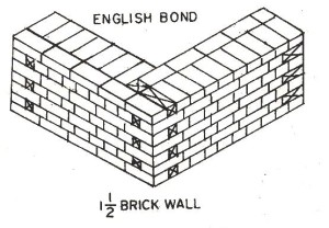
English bond consists of alternate course of headers and stretches. In this English bond arrangement, vertical joints in the header courses come over each other and the vertical joints in the stretcher course are also in the same line. For the breaking of vertical joints in the successive course it is essential to place queen closer, after the first header in each heading course. The following additional points should be noted in English bond construction:
(1) In English bond, a heading course should never start with a queen closer as it is liable to get displaced in this position.
(2) In the stretcher course, the stretchers should have a minimum lap of 1/4th their length over the headers.
(3) Walls having their thickness equal to an even number of half bricks, i.e., one brick thick wail, 2 brick thick wall, 3 brick thick wall and so on, present the same appearance on both the faces, i .e. a course consisting of headers on front face will show headers on the back face also.
Isometric view of  1½ brick wall in English bond is shown below,
English bond
(4) In walls having their thickness equal to an odd number of half brick, i.e. 1½ brick thick walls or 2½ brick thick walls and so on, the same course will show stretchers on one face and headers on the other.
(5) In thick walls the middle portion is entirely filled with header to prevent the formation of vertical joints in the body of the wall.

(6) Since the number of vertical joints in the header course is twice the number of joints in the stretcher course, the joints in the header course are made thinner than those in the stretcher course.
2. Flemish bond:
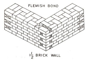
In Flemish bond, each course consists of alternate headers and stretchers. The alternate headers of each course are centered over the stretchers in the course below. Every alternate course starts with a header at the corner. For the breaking of vertical joints in the successive courses, closers are inserted in alternate courses next to the quoin header. In walls having their thickness equal to odd number of half bricks, bats are essentially used to achieve the bond.
Flemish bond is further divided into two different types namely,
a. Single Flemish bond,
b. Double Flemish bond.
Flemish Bond
a. Single Flemish Bond.
This bond is a combination of English bond and Flemish bond.  In this work the facing of the wall consists of Flemish bond and the backing consists of English bond in each course. This type of bonding cannot be adopted in walls less than one and a half brick in thickness. This bond is adopted to present the attractive appearance of Flemish bond with an effort to ensure full strength in the brick work.
b. Double Flemish bond.
In Double Flemish Bond, each course presents the same appearance both in the front and back elevations. Every course consists of headers and stretchers laid alternately. This type of bond is best suited from considerations of economy and appearance. It enables the one brick wall to have flush  and uniform faces on both the sides. This type of bonding is comparatively weaker than English bond.
3. Stretching bond:
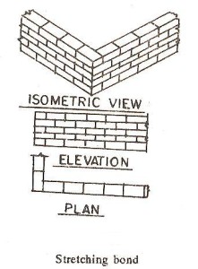
In this arrangement of bonding, all the bricks are laid as stretchers. The overlap, which is usually of half brick, is obtained by commencing each alternate course with a half brick bat. Stretching bond is used for half brick wall only. This bond is also termed as running bond and is commonly adopted in the construction of half brick thick leaves of cavity walls, partition walls, etc. Since there are no headers, suitable reinforcement should be used for structural bond.
Stretching Bond
4. Heading bond :
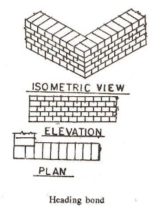
In this type of bonding all the bricks are laid as headers on the faces. The overlap, which is usually-of half the width of the brick is obtained by introducing a three-quarter bat in each alternate course at quoins. This bond permits better alignment and  as such it is used for walls curved on plan. This bond is chiefly used for footings in foundations for better transverse distribution of load.
Heading Bond
5.Garden wall bond:
This type of bond is suitably adopted for one brick thick wall which may act as a garden wall or a boundary wall. In garden wall bond, it is possible to build uniform faces for a wall without much labour or expense. This type of bond is not so strong as English bond and its use is restricted to the construction of dwarf walls or other similar types of walls which are not subjected to large stresses. On accounts of its good appearance, this bond is sometimes used for the construction of the outer leaves of cavity walls.
There are two types of garden wall bond,
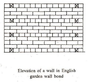
(a) English garden wall bond
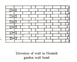
(b) Flemish garden wall bond
(a) English garden wall bond. The general arrangement of bricks in this type of bonding is similar to that of English bond except that the heading courses are only inserted at every fourth or sixth course. Usually the arrangement consists of one course of headers to three courses of stretchers. A queen closer is placed next to the quoin header of the heading course to give the necessary lap.
English garden wall bond
(b) Flemish garden wall bond. This consists of alternate course composed of one header to three or sometimes even five stretchers in series throughout the length of the courses. Each alternate course contains a three quarter bat placed next to the quoin header and a header is laid over the middle of each central stretcher.
Flemish Garden wall bond
6.Facing bond:
This arrangement of bricks is adopted for thick walls, where the facing and backing are desired to be constructed with bricks of different thickness. This bond consists of heading and stretching courses so arranged that one heading course comes after several stretching courses. Since the number of joints in the backing and the facing differ greatly, the load distribution is not uniform. This may sometimes lead to unequal settlement of the two thickness of the wall.
7.Raking bond:
This is a bond in brick work in which the bonding bricks are laid at any angle other than zero or ninety degrees. This arrangement helps to increase the longitudinal stability of thick walls built in English bond. In this arrangement of bonding, the space between the external stretchers of a wall is filled with bricks inclined to the face of the wall. This bond is introduced at certain intervals along the height of a wall.
There arc two common forms of raking bond ;
(a) Herring hone bond
(b) Diagonal bond.
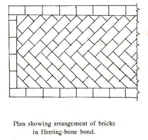
(a) Herring-bone bond. This type of bond is best suited for very thick walls usually not less than four bricks thick. In this arrangement of brick work, bricks are laid in course inclined at 45° in two directions from the centre. This bond is also commonly used for brick pavings.
Herring-bone bond
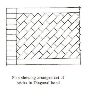
(b) Diagonal bond. This bond is best suited for walls which are 2 to 4 brick thick. This bond is usually introduced at every fifth or seventh course along the height of the wall. In this bond, the bricks arc placed end to end in such a way that extreme corners of the series remain in contact with the stretchers.
Diagonal Bond
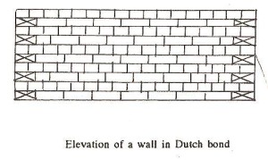
8.Dutch bond:
This bond is a modification of the old English cross bond and consists of alternate courses of headers and stretchers. In this arrangement of brick work, each stretching course starts at the quoin with a three-quarter bat and every alternate stretching course has a header placed next to the three-quarter brick bat provided at the quoin.
Dutch Bond
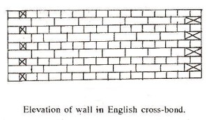
9.English cross-bond:
This is similar to English bond and consists of alternate course of headers and stretchers. However, in this bond, queen closer are introduced next to quoin headers and each alternate stretching course has header placed next to quoin stretcher. This bond is sufficiently strong and bears a good elevation.
English Cross Bond
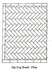
10. Zig-Zag bond:
This is similar to herring-bone bond with the only difference that in this case the bricks are laid in a zig-zag fashion. This is commonly adopted in brick paved flooring.
Zig zag bond
11. Silverlock’s bond:
This is a form of bonding brick-work in which bricks are laid on edge. It is economical but weak in strength and hence it is only recommended for garden walls or partition walls. In this bond, the bricks are laid as headers and stretchers in alternate courses in such a way that headers are laid on bed aid the stretchers are laid on edge forming a continuous cavity.

Tuesday 8 August 2017

Civil Engineering And Structural Engineering


Civil Engineering And Structural Engineering


CIVIL ENGINEERING

Define:-
              Civil Engineering and Structural Engineering are two disciplines in the field of engineering which deals with evaluation, design construction and preservation of elements. Generally, structural engineering is categorized as an area of specialization of civil engineering. But through the years, modern development in science and architecture has made structural engineering into a separate discipline.

The difference between civil engineering and structural engineering is tricky. The task of discerning the two terms would be difficult without first understanding the concept behind each line of work.


Civil Engineering
                                     Civil Engineering is considered as one of the oldest fields in engineering. Its history dates back to when people started building a shelter for themselves. This engineering field is offered in universities as a first-degree course and includes disciplines such as transportation engineering, Geotechnical engineering, environmental engineering and structural engineering.

Structural Engineering
                                          Structural engineering involves the analysis, design, construction, and maintenance of structures that reinforce or counteract loads, such as skyscrapers, dams, and bridges.

This engineering field is offered in universities as both a subject under civil engineering and a specialization that result in a master's degree or a doctorate.

The Difference between Civil Engineering and Structural Engineering

Although they may belong to the same field of engineering, they differ in several aspects. For example, civil engineering focuses more attention in design elements while structural engineering is more concern on inspecting materials to be used for the construction. They ensure that the materials being used for construction can support the design of the structure.

To sum it up, civil engineering is a broad subject which covers structural engineering. It’s a first-degree course offered in universities which result in a bachelor degree. On the other hand, structural engineering is a subject under civil engineering and is taught to students taking up the course. However, it is also a specialization which leads to a master's degree or a doctorate.

In reality, their difference and similarities are not that important, the important thing is that they are both crucial knowledge needed by the construction industry. Engineering firms, such as Godfrey-Hoffman & Hodge in Connecticut, provide both civil engineering and structural engineering services to customers because they understand that they are both essential in any construction work or development project.

Monday 7 August 2017

BRIDGE ENGINEERING


Bridge:-

Structure that spans horizontally between supports, whose function is to carry vertical loads. The prototypical bridge is quite simple—two supports holding up a beam—yet the engineering problems that must be overcome even in this simple form are inherent in every bridge: the supports must be strong enough to hold the structure up, and the span between supports must be strong enough to carry the loads. Spans are generally made as short as possible; long spans are justified where good foundations are limited—for example, over estuaries with deep water.

All major bridges are built with the public’s money. Therefore, bridge design that best serves the public interest has a threefold goal: to be as efficient, as economical, and as elegant as is safely possible. Efficiency is a scientific principle that puts a value on reducing materials while increasing performance. Economy is a social principle that puts value on reducing the costs of construction and maintenance while retaining efficiency. Finally, elegance is a symbolic or visual principle that puts value on the personal expression of the designer without compromising performance or economy. There is little disagreement over what constitutes efficiency and economy, but the definition of elegance has always been controversial.

Generally speaking, bridges can be divided into two categories: standard overpass bridges or unique-design bridges over rivers, chasms, or estuaries. This article describes features common to both types, but it concentrates on the unique bridges because of their greater technical, economic, and aesthetic interest

The Elements Of Bridge Design

There are six basic bridge forms: the beam, the truss, the arch, the suspension, the cantilever, and the cable-stay.


Beam

The beam bridge is the most common bridge form. A beam carries vertical loads by bending. As the beam bridge bends, it undergoes horizontal compression on the top. At the same time, the bottom of the beam is subjected to horizontal tension. The supports carry the loads from the beam by compression vertically to the foundations.
When a bridge is made up of beams spanning between only two supports, it is called a simply supported beam bridge. If two or more beams are joined rigidly together over supports, the bridge becomes continuous.

Bridge Engineering – Components of Bridge Structures

A bridge is a structure providing passage over an obstacle without closing the way beneath. The required passage may be for a road, a railway, pedestrians, a canal or a pipeline. The obstacle to be crossed may be a river, a road, railway or a valley.
components of bridge

components of bridge

 Classification of Bridges

Classification of Bridges (According to form (or) type of superstructures)
  1. Slab bridge
  2. Beam bridge
  3. Truss bridge
  4. Arch bridge
  5. Cable stayed (or )suspended bridge
 Classification of bridges (According to material of construction of  superstructure)
  1. Timber bridge
  2. Concrete bridge
  3. Stone  bridge
  4. R.C.C bridge
  5. Steel bridge
  6. P.C.C bridge
  7. Composite bridge
  8. Aluminum bridge
Scherzer Rolling Lift Bridge
 Classification of bridges (According to inter-span relationship)
  1. Simply supported bridge
  2. Cantilever  bridge
  3. Continuous  bridge
 Classification of bridges (According to the position of the bridge floor relative to superstructures)
  1. Deck through bridge
  2. Half through or suspension  bridge
 Classification according to method of connection of different part of superstructures
  1. Pinned connection  bridge
  2. Riveted connection  bridge
  3. Welded connection  bridge
New River Gorge Bridge made of weather resistant steel
According to length of bridge
  1. Culvert  bridge(less than 6 m)
  2. Minor bridge(less than 6 m-60m)
  3. Major bridge(more than 60 m)
  4. Long span bridge(more than 120 m)
According to function
  1. Aqueduct bridge(canal over a river)
  2. Viaduct(road or railway over a valley or river)
  3. Pedestrian bridge
  4. Highway bridge
  5. Railway bridge
  6. Road-cum-rail or pipe line bridge
Check the pdf